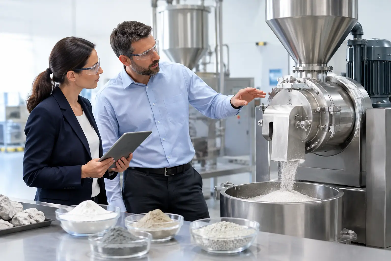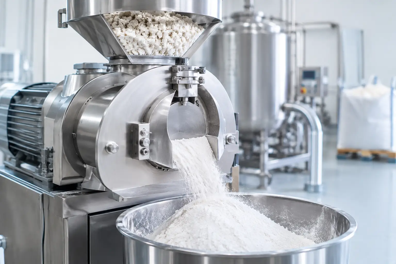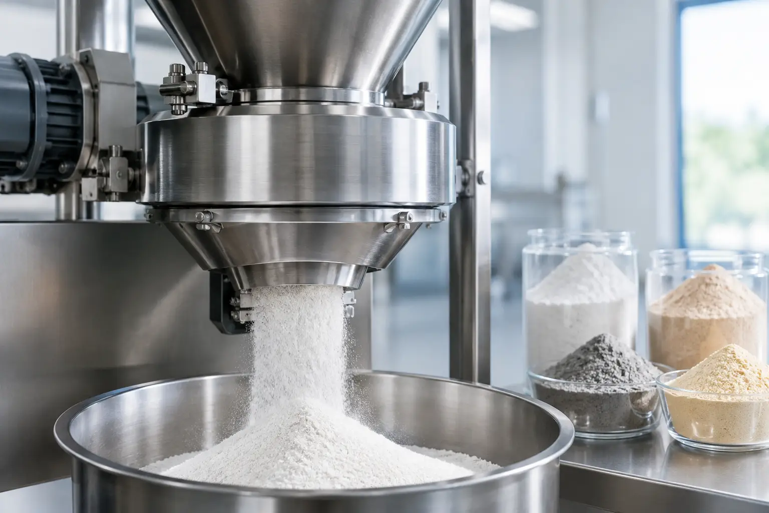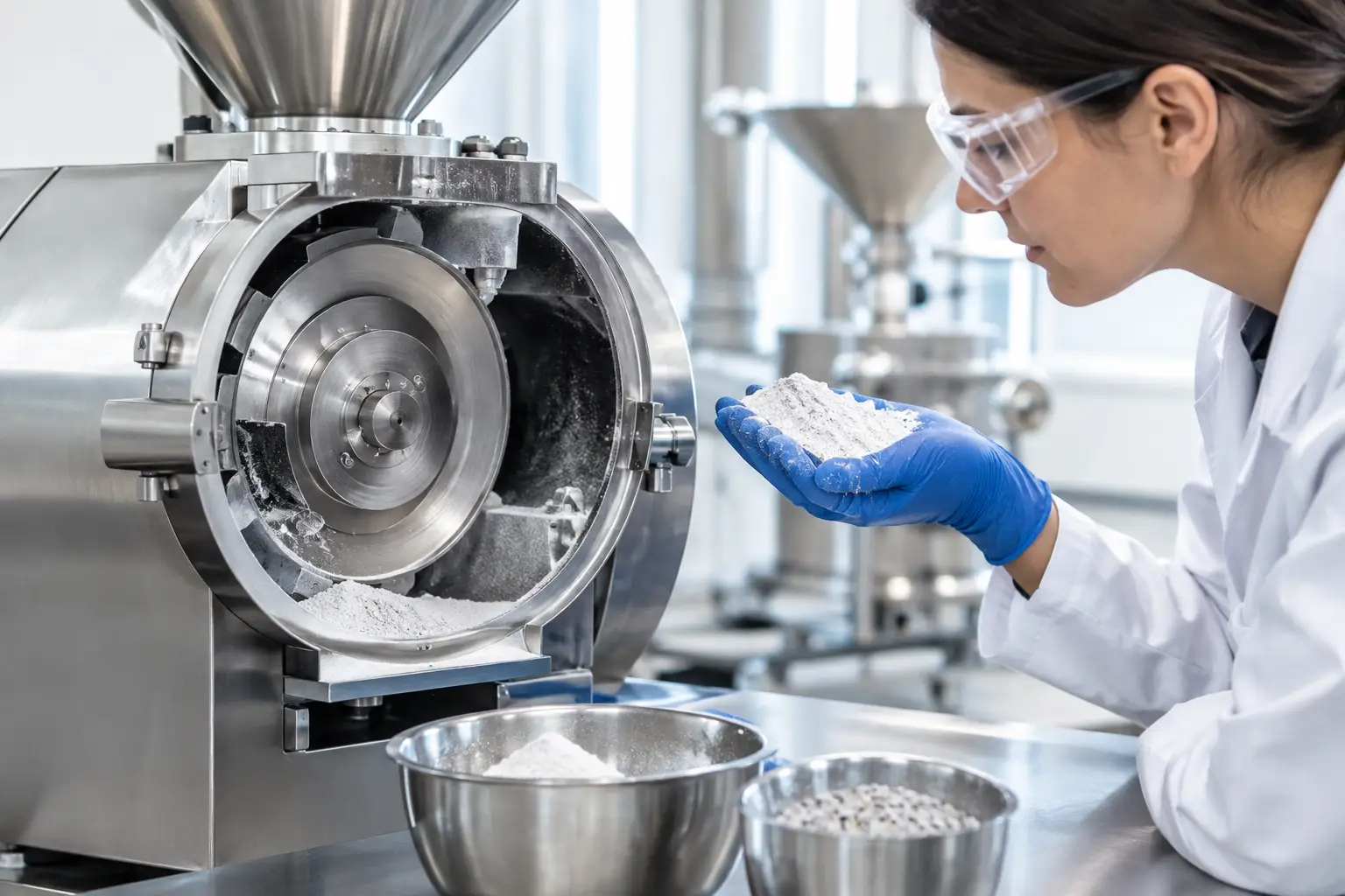
A mill rarely fails at a convenient time. The real cost is not limited to the replacement bearing, worn rotor, or blocked screen. It includes lost production, delayed downstream packaging, labor spent troubleshooting, material held in process, and the risk of producing off-spec powder while the problem develops. Knowing how to reduce milling downtime starts with treating the mill as part of an integrated process, not as an isolated machine.
For pharmaceutical, food, chemical, battery, mineral, and advanced-material operations, the most effective uptime strategy combines equipment selection, preventive maintenance, material control, and operating discipline. The right priorities depend on the material and mill type, but the objective is consistent: keep the process within a stable operating window before a small deviation becomes an unplanned shutdown.
Find the Actual Cause of Milling Downtime
Plants often label a stoppage as a mechanical failure when the underlying cause began upstream or downstream. A pin mill may overload because the feeder surges. A jet mill may lose performance because compressed air quality has deteriorated. A hammer mill may plug because incoming material moisture has changed. Replacing components without identifying these conditions can shorten the time until the next event, but it does not solve the downtime problem.
Start by categorizing every stoppage with enough detail to identify patterns. Record the mill, material lot, product moisture, feed rate, target particle size, operating speed or pressure, screen or classifier configuration, duration of the interruption, and corrective action taken. A simple record becomes valuable when it distinguishes between repeated minor interruptions and true equipment failures.
Four recurring causes deserve particular attention:
- Feed inconsistency, including bridging, surging, foreign material, excessive moisture, and poor bulk density control.
- Wear in high-contact components such as hammers, pins, liners, screens, classifier wheels, nozzles, bearings, and seals.
- Process conditions outside the proven operating range, including excessive throughput, poor air balance, incorrect rotor speed, or inadequate cooling.
- Cleaning and changeover practices that require excessive disassembly or create opportunities for reassembly errors.
This analysis should include planned downtime as well. A mill that runs reliably but requires an eight-hour changeover may still be the constraint that limits the entire line.
How to Reduce Milling Downtime With Condition-Based Maintenance
Calendar-based maintenance remains necessary for safety-critical inspections and known wear intervals, but it can be inefficient when used alone. Components do not always wear at the same rate. Abrasive minerals, fibrous botanicals, hygroscopic powders, and hard battery materials create very different loads on a milling system.
Condition-based maintenance uses operating evidence to determine when intervention is required. Trending motor amperage, vibration, bearing temperature, differential pressure, airflow, compressed-air consumption, and particle size distribution can reveal degradation before the mill stops. For example, rising motor load at a constant feed rate may point to screen blinding, rotor wear, buildup, or a change in material behavior. A gradual shift in product fineness can indicate worn internal components or a classifier that is no longer operating as intended.
The goal is not to install every available sensor. It is to monitor the variables that reflect the failure modes most likely in the application. A hammer mill handling abrasive material may benefit from vibration and motor-load trending. An air classifier mill may require close attention to classifier speed, process air volume, and differential pressure. In a jet milling system, stable air pressure, air dryness, and nozzle condition can be central to uptime and product consistency.
Maintenance plans should also account for access. If replacing a wear component requires extended teardown, inventory the parts that commonly limit production and establish a documented replacement procedure. Keeping critical spares on site is practical only when part usage, lead time, and production risk justify it. Overstocking every component increases carrying cost without improving reliability.
Stabilize the Feed Before It Reaches the Mill
Milling equipment cannot compensate indefinitely for unstable incoming material. Feed variability drives a large share of plugging, overheating, throughput loss, and particle-size variation. The material must arrive at the mill in a condition the system is designed to process.
Moisture is often the first variable to investigate. Material that is slightly wetter than normal can smear across screens, form deposits on internal surfaces, bridge in hoppers, or reduce the efficiency of air classification. Conversely, an overly dry, electrostatically charged powder may create transfer and containment challenges. The correct moisture range depends on the product, not a universal setpoint.
Particle size and bulk density entering the mill also matter. Oversized lumps can overwhelm a fine-grinding stage, while broad feed distributions can make it harder to maintain a tight finished specification. Upstream sizing, de-lumping, screening, drying, or conditioning may reduce milling interruptions more effectively than changes to the mill itself.
Feeding hardware requires the same engineering attention as the mill. A properly selected screw feeder, vibratory feeder, rotary valve, or loss-in-weight system should deliver material at a controlled and repeatable rate. Poor hopper geometry, inadequate agitation, or an improperly sized feeder can produce surges that look like a mill problem. For cohesive or low-density materials, flow testing and feeder trials are usually more valuable than relying on generic feeder assumptions.
Design for Faster Cleaning and Changeovers
In regulated and multi-product facilities, planned cleaning can consume more time than mechanical repairs. The trade-off is especially clear in pharmaceutical, nutraceutical, food, and specialty chemical applications, where cross-contamination control cannot be compromised for speed.
The answer is not to reduce cleaning requirements. It is to engineer the system so cleaning is repeatable, accessible, and appropriate for the material hazard and product-quality requirements. Smooth internal surfaces, sanitary construction where needed, minimized product hold-up areas, quick-release access points, and logical disassembly sequences can significantly reduce changeover time.
A documented cleaning procedure should identify component orientation, inspection points, approved tools, torque requirements, and verification steps before restart. Photos and visual work instructions are particularly useful when operators work across multiple mill configurations. A rushed reassembly can create avoidable vibration, leakage, poor sealing, or product contamination.
For difficult materials, consider whether a different process configuration would reduce cleaning burden. Cryogenic grinding can help materials that become sticky or heat-sensitive during ambient milling. An air-classifying approach may reduce recirculation of coarse material. In some applications, a dedicated process line produces better long-term economics than frequent product changeovers on a shared mill.
Operate Within a Proven Process Window
High utilization does not mean operating at the highest possible feed rate every shift. Pushing a mill beyond its stable range can create a cycle of overloads, quality holds, cleanup, and premature wear. The best operating point balances throughput, particle size, temperature, energy use, and component life.
Develop a process window during trials or production qualification. Define acceptable ranges for feed rate, mill speed, air volume, classifier speed, temperature, pressure, and product characteristics. Operators need clear limits and a defined response when values drift. If a parameter exceeds its range, the response may be to reduce feed, inspect the feeder, verify airflow, or stop the system before damage occurs.
This is also where automation can be valuable. Interlocks, load-based feed control, vibration alarms, temperature monitoring, and trend reporting help operators respond consistently. Automation should support sound process knowledge, not mask an unstable system. A control loop cannot correct a feeder that is bridging or a mill that is incorrectly sized for the required duty.
Match the Mill to the Material and Production Duty
Some downtime is built into a poor equipment fit. A mill selected only for initial capacity may lack the wear resistance, containment capability, cooling capacity, or cleanability required for sustained production. This is common when an application moves from pilot quantities to full-scale output without reassessing material behavior and duty cycle.
Mill selection should consider hardness, abrasiveness, friability, heat sensitivity, fat or oil content, moisture, required particle size distribution, contamination limits, explosion risks, and cleaning requirements. A universal mill, pin mill, hammer mill, jet mill, turbo mill, cone mill, or air classifier mill may each be appropriate under different conditions. No single technology is best across all materials.
System integration matters just as much. Dust collection, conveying, air handling, feeding, classification, discharge, and controls all influence mill availability. DP Mills approaches these variables as a complete particle-processing system because a reliable milling line depends on how each component performs with the others.
Turn Downtime Data Into Better Decisions
The most useful reliability improvement is often a small, targeted change supported by data: a revised feeder setting, a more suitable screen, a wear-resistant liner, an improved cleaning sequence, or an earlier inspection threshold. Review downtime trends regularly with operations, maintenance, and quality teams so the solution addresses production reality rather than a single department’s perspective.
When repeated stoppages persist, treat them as an engineering question. Confirm the material properties, observe the system in operation, and test the assumptions behind the existing process. A mill that remains stable through normal variation in feed and operating conditions gives the plant more than uptime. It gives operators the confidence to run predictably, protect product quality, and plan production around performance instead of interruptions.