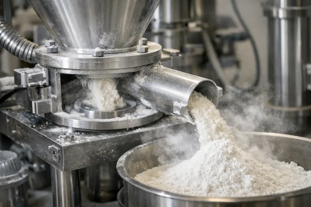
A powder can meet particle-size specifications at the mill discharge and still fail in the next process step because its temperature rose too far during size reduction. Lost potency, softened fats, altered crystal structure, agglomeration, poor flow, flavor loss, and screen blinding can all begin with excess process heat. Understanding how to prevent powder heat buildup requires more than adding cooling air. It requires controlling the energy entering the material, removing that energy effectively, and monitoring the process conditions that change from one production run to the next.
Why Powder Heat Buildup Occurs During Milling
Nearly all mechanical milling converts part of its input energy into heat. In hammer mills, pin mills, turbo mills, and universal mills, particle-to-rotor impact and particle-to-particle collisions create heat directly. In air classifier mills, recirculating oversized particles can receive repeated impacts before reaching the target cut size. Even in a jet mill, where compressed gas provides the grinding energy, the gas system, feed conditions, and downstream collection system affect the material temperature.
The severity of heat buildup depends on the material and the process. A hard mineral may tolerate a substantial temperature rise with little change in quality. A nutraceutical containing heat-sensitive actives, a food powder with oil content, or a polymer near its softening point may have a very narrow operating window. Fine grinding raises the risk because producing smaller particles requires more energy and increases the surface area available for friction, adhesion, and moisture interaction.
Feed rate is often a major variable. Underfeeding can leave too little material in the grinding zone, allowing particles to receive excessive impact energy. Overfeeding can create bed compaction, elevated motor load, reduced airflow, and recirculation. The correct rate is not simply the highest throughput the mill can accept. It is the rate that maintains the required particle size, temperature, and stable material movement through the system.
Start With a Measured Heat Profile
A useful heat-control program begins with data rather than assumptions. Measure feed temperature, mill discharge temperature, product temperature at collection, inlet and outlet air temperatures, airflow, pressure drop, rotor speed, motor load, and feed rate. For products with a tight temperature limit, continuous temperature measurement at the discharge and collector is preferable to intermittent hand checks.
The difference between mill discharge temperature and product temperature at packaging can be revealing. A powder may leave the mill within specification but heat further in a cyclone, filter receiver, or packed container if residence time is high or cooling is inadequate. Conversely, a high temperature reading at one location may reflect warm conveying air rather than a material temperature problem. The measurement point and sensor placement matter.
Trend data across a complete run. A process that starts cool but drifts upward after 30 minutes may be experiencing filter loading, reduced airflow, worn grinding components, or heat soak in the mill housing. A sudden temperature increase may point to a bridging feed hopper, a change in raw material moisture, or an operating adjustment made upstream.
Control the Energy Going Into the Powder
Match Mill Technology to the Material
The most effective way to control heat is to avoid applying more mechanical energy than the application requires. Hammer, pin, and turbo mills can provide high throughput and practical size reduction for many materials, but their operating speed and screen selection must be matched to product behavior. Running a high-speed impact mill at maximum speed to achieve a minor reduction in top size can create unnecessary heat, fines, and wear.
An air classifier mill may provide a better solution when narrow particle size control is necessary because classifier speed can manage the cut point. However, an aggressive classifier setting can increase internal recirculation and residence time, which can raise temperature. The best operating point balances rotor speed, classifier speed, airflow, and feed rate rather than treating each control as independent.
For highly heat-sensitive, oily, waxy, elastic, or low-melting materials, cryogenic grinding may be the appropriate process choice. Introducing a cryogenic medium can embrittle the feed and reduce the energy needed for fracture while keeping material temperatures below a defined limit. It adds utility consumption and system complexity, so it should be selected when ambient or chilled milling cannot achieve the required quality and throughput.
Set Rotor Speed for the Required Result
Higher tip speed generally increases impact force, but it also raises heat generation. The correct approach is to establish the minimum rotor speed that consistently achieves the target particle size distribution. This may involve adjusting screen size, classifier settings, or feed conditioning rather than relying on speed alone.
Do not assume that a slower rotor always produces a cooler process. If lower speed causes large particles to remain in the chamber longer, total energy exposure can rise. A controlled trial should compare product temperature, particle size distribution, throughput, mill load, and yield at several operating points. The best setting is the one that produces stable performance, not just the lowest instantaneous temperature.
Maintain a Consistent, Metered Feed
A loss-in-weight feeder, screw feeder, or other metering device should deliver material evenly into the milling zone. Surging feed creates alternating periods of underloading and overloading, both of which can increase heat and particle-size variability. Hopper agitation, bin design, and material flow aids may be needed for cohesive powders, but they should be evaluated for contamination risk and impact on bulk density.
Raw material condition is equally important. Moisture changes can alter grindability, promote screen blinding, and increase adhesion to internal surfaces. Temperature changes in incoming material can narrow the available process margin before milling even starts. Establish feed specifications for moisture, initial temperature, bulk density, and particle form when these variables affect performance.
Remove Heat With Airflow and Cooling
Process airflow removes heat, transports particles, and supports classification in many milling systems. Insufficient airflow allows heat to accumulate in the grinding chamber and increases powder residence time. Excessive airflow can reduce classification efficiency, carry oversize material downstream, or create collection challenges. Air volume, static pressure, and system resistance must be evaluated as a connected system that includes the mill, ductwork, cyclone, filters, and receiver.
Conditioned process air can provide meaningful control. Ambient air may be sufficient for products with moderate thermal sensitivity, particularly when airflow is stable and the mill is correctly loaded. Chilled, dehumidified air can expand the operating window where humidity or warm plant conditions contribute to caking and temperature rise. For certain applications, closed-loop gas systems may be appropriate for moisture control, oxidation prevention, solvent handling, or very low-temperature operation.
Cooling jackets on the mill housing, bearing zones, or classifier section can reduce heat transfer into the product. They are most effective when paired with suitable operating conditions. A jacket cannot compensate for severe overmilling, poor airflow, or a material that is fundamentally unsuitable for ambient mechanical grinding. It also requires attention to condensation control, especially in humid environments or sanitary operations.
Reduce Friction, Residence Time, and Heat Soak
Wear is a heat-management issue as well as a maintenance issue. Worn hammers, pins, liners, screens, and classifier components can reduce milling efficiency, extend residence time, and create inconsistent particle trajectories. Product buildup on internal surfaces has a similar effect. Establish inspection intervals based on process data, not only calendar schedules.
Screen selection deserves particular attention in screen-based mills. A screen that is too fine can restrict discharge, raise residence time, and drive up product temperature. If a finer final particle size is required, a staged process may be more effective than forcing all reduction through one restrictive screen. Pre-sizing followed by a controlled fine-grinding step can improve capacity and reduce thermal exposure.
Downstream equipment must also release heat. Long conveying paths, undersized cyclones, overloaded filters, and slow product discharge can retain warm powder after it leaves the mill. If packaging temperature is critical, include a cooling or conditioning step before filling containers. Dense, insulated containers can hold heat long enough to create caking or quality changes after production is complete.
Build Temperature Control Into Process Development
The most reliable answer to how to prevent powder heat buildup is to define temperature as a process requirement during development, alongside particle size, throughput, yield, and contamination limits. Pilot trials should identify both the preferred operating point and the boundaries where temperature begins to affect product quality. That information supports scale-up, control limits, and operator response procedures.
At DP Mills, this evaluation is approached as a complete processing system question, from feed behavior and milling technology through air handling and collection. A mill selected only by capacity or target micron size may meet neither the product temperature requirement nor the long-term reliability expected in production.
Set practical alarm limits before the product reaches its maximum allowable temperature. When a trend approaches that limit, operators should know whether to adjust feed rate, rotor speed, airflow, cooling capacity, or the upstream material condition. Clear response steps prevent a minor thermal drift from becoming a rejected batch.
A stable thermal process is rarely the result of one adjustment. It comes from matching the equipment and controls to the material, then verifying that the complete system continues to perform as production conditions change.