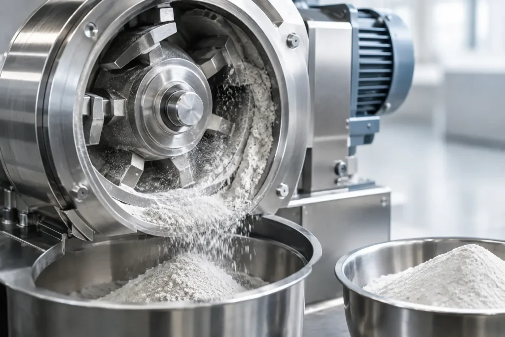
A worn rotor, liner, or classifier wheel rarely fails at a convenient time. It first shows up as declining throughput, a broader particle size distribution, unexpected metal contamination, or rising power draw. Effective mill wear reduction addresses these early signals by treating wear as a process-design issue, not simply a maintenance expense.
For manufacturers processing abrasive minerals, battery materials, chemicals, food ingredients, or high-value pharmaceutical powders, the goal is not to eliminate all wear. Every size reduction process transfers energy into material, and some component loss is inevitable. The practical objective is to control wear rates, protect product purity, extend planned run time, and make wear-part replacement predictable.
Why Mill Components Wear
Wear occurs when feed material repeatedly contacts and moves across internal process surfaces. The dominant mechanism depends on the material, mill design, and operating conditions. Abrasion occurs when hard particles cut or scrape a surface. Impact wear occurs when particles strike components at high velocity. Erosion is common where an accelerated air stream carries abrasive fines around bends, classifier zones, and discharge paths.
Corrosion can also contribute, particularly with reactive products, humid air, aggressive cleaning agents, or temperature-sensitive chemistries. In many applications, several mechanisms are active at once. A hard, angular mineral processed at high tip speed may abrade rotor surfaces while eroding the classifier and discharge piping. A sticky material may create buildup that changes the effective grinding geometry, causing localized wear and higher heat generation.
The cost reaches beyond replacement parts. Progressive wear can alter the mill’s internal clearances and airflow pattern. That affects residence time, classification efficiency, particle size control, and energy consumption. In regulated or contamination-sensitive applications, worn metallic surfaces can also introduce foreign material risk that requires additional inspection, screening, or batch disposition.
Mill Wear Reduction Starts With the Right Process
The most durable wear solution is often selected before equipment is built. Milling technology should match the feed material’s hardness, brittleness, moisture behavior, heat sensitivity, target particle size, and purity requirements. A mill that produces an acceptable laboratory result may not provide acceptable wear life at production throughput.
For example, a jet mill can reduce mechanical contact in the grinding zone because particle-to-particle collisions perform much of the size reduction. This can be advantageous for abrasive materials requiring fine particle sizes and tight classification. However, high-velocity gas streams still expose nozzles, classifiers, and product-contact surfaces to erosion. The system must be engineered with appropriate materials and air velocity for the application.
Hammer mills, pin mills, and turbo mills offer efficient processing across many materials, but their rotating elements and liners require careful selection when feed is abrasive. Reducing tip speed may extend component life, but it can also shift the particle size distribution or reduce capacity. The correct decision depends on the production objective. If a slightly coarser product is acceptable, operating at lower speed may deliver a meaningful reduction in wear and energy use. If the specification demands a fine cut, material upgrades or a different milling configuration may be the better answer.
Air classifier mills require a similar systems view. The mill and classifier cannot be evaluated independently. Wheel speed, airflow, feed rate, and internal circulation determine both final size and the abrasion load on the classifier. Operating a classifier wheel faster than necessary may produce a finer product, but it may also increase recirculation, accelerate wear, and reduce net throughput.
Characterize the Feed Before Selecting Wear Materials
Material hardness alone does not predict wear. Particle shape, feed size, bulk density, moisture, flowability, and the presence of trace contaminants all matter. Sharp, irregular particles can be more aggressive than rounded particles with a similar hardness value. Large oversize particles can create concentrated impact damage even when the average feed is relatively fine.
A useful process evaluation considers the feed size distribution, target specification, expected annual tonnage, operating schedule, and allowable contamination level. It should also account for variability in incoming material. A mill designed around ideal feed may wear rapidly when normal supplier variation introduces larger or harder particles.
Select Contact Materials for the Actual Duty
Wear-resistant alloys, hardened tool steels, ceramics, tungsten carbide, and engineered coatings can improve service life, but no single material is right for every process. The best choice balances wear resistance, impact resistance, cleanability, contamination requirements, fabrication constraints, and cost.
Hard coatings and ceramics can perform exceptionally well in abrasive service, especially where sliding abrasion dominates. Yet very hard materials may be vulnerable to cracking under severe impact, thermal cycling, or improper installation. Tungsten carbide offers strong abrasion resistance for many high-wear components, but it may be unnecessary in lower-duty zones where a hardened alloy provides a more economical lifecycle result.
Contamination requirements often narrow the options. Pharmaceutical, food, nutraceutical, and specialty chemical operations may need stainless steel construction, polished surfaces, or nonmetallic contact materials to support sanitation and product integrity. Battery and advanced-material producers may require tightly controlled metallurgy to prevent unacceptable trace-metal introduction. In these applications, the lowest-wear material is not automatically the correct material if it creates a product-quality risk.
Wear protection should be applied selectively. High-velocity turns, feed inlets, rotor leading edges, classifier components, impact zones, and discharge elbows frequently deserve the greatest attention. Specifying premium materials across every surface can increase capital cost without proportional value. An engineered wear map identifies where protection will produce the largest return.
Operate Within the Mill’s Stable Range
Even a well-designed mill will wear prematurely when operated outside its stable process window. Excessive feed rate can overload the grinding chamber, increase recirculation, and force particles against internal surfaces more frequently. Insufficient feed can expose components to direct high-velocity air or cause inefficient grinding behavior. Both conditions can shorten useful life.
Control of feed rate, rotor speed, classifier speed, airflow, and inlet temperature is central to wear management. These variables interact. Raising airflow may improve transport and cooling but can increase erosive velocity in selected zones. Increasing rotor speed may improve breakage but adds impact energy. A process change that solves one problem can create another, which is why adjustments should be evaluated through production data rather than isolated observations.
Four operating conditions deserve routine review:
- Feed size and hardness changes that alter impact loading.
- Higher-than-normal mill speed or classifier speed used to chase a finer cut.
- Airflow imbalance, leaks, or duct geometry that create erosive hot spots.
- Product buildup that narrows passages and changes internal flow patterns.
Trend operating data against wear inspections. If power draw rises while throughput falls, the cause may be buildup, worn screens, altered clearances, or a changing feed. If product becomes coarser at the same settings, worn hammers, pins, liners, or classifier elements may be reducing effective grinding and separation performance.
Design the Full System, Not Just the Mill
Wear often originates outside the main grinding chamber. Improper feed introduction can send large particles into a rotor at unfavorable angles. Poorly designed transitions, elbows, valves, and conveying lines can erode rapidly and generate contamination before material reaches the collector. Dust collection performance also matters. Unstable system pressure can change airflow through the mill and alter both milling results and wear patterns.
A properly integrated system uses controlled feeding, suitable air handling, gradual transitions where practical, and access points for inspection. It also considers the behavior of the material after milling. If warm, fine powder accumulates in a restrictive discharge path, the resulting buildup may cause backpressure that changes mill performance upstream.
For heat-sensitive or difficult materials, cryogenic grinding can reduce softening, smearing, and material adhesion. This can indirectly reduce wear by preserving free-flowing product behavior and limiting deposits on process surfaces. It is not a universal solution, since cooling adds operating complexity and utility cost, but it can be valuable where conventional milling creates heat-driven process instability.
Make Inspection and Replacement Predictable
Planned inspections are more effective than waiting for visible performance loss. Establish baseline measurements for critical components during commissioning, then inspect at intervals based on material severity and production hours. Measure liner thickness, rotor dimensions, classifier condition, screen integrity, and clearances that influence product quality.
Replacement decisions should consider process performance as well as remaining physical thickness. A component can appear serviceable yet no longer hold the geometry needed for consistent particle size. Conversely, changing a wear part too early can waste useful life. The right interval is established through documented wear rates, production trends, and quality results.
Maintain critical spares for components that control uptime, especially when specialized materials or custom geometries have longer lead times. Standardizing wear parts across compatible equipment where possible can simplify inventory, but standardization should not override application-specific engineering.
At DP Mills, wear considerations are evaluated as part of the milling system and the material process, including equipment configuration, contact materials, operating conditions, and downstream handling. That approach helps manufacturers move from reactive repairs to a controlled maintenance strategy built around production requirements.
The most productive next step is to examine where wear is occurring, what changed before it accelerated, and whether the current mill configuration is asking one component to solve a broader process problem. Those answers usually point to the most cost-effective path toward longer runs and more consistent product.